Proposed: Target Deployment Architecture
The multi-AZ Oracle Cloud architecture this deployment is growing towards, what is in place today, and the four gaps between them. Aspirational — nothing on this page is running yet.
On this page
Status: proposed. Not the deployment you have.
Everything on this page describes an end state the platform is growing towards. The architecture running today is Deploy on Oracle Cloud: one Compute instance, one managed PostgreSQL, one Load Balancer. Where this page and that page disagree, that page is the truth. Nothing here is a prerequisite for anything, and no step below should be attempted as part of a rollout.
The reason for publishing it as a document rather than leaving it in a slide is that it is the shared target: it decides which components the platform team provisions, which ones the software has to grow, and — the part that is easy to lose — which of them nobody has built yet.
The proposed architecture
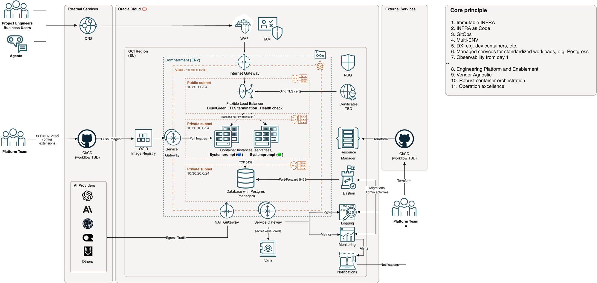
The principles it is built on are the platform team's: immutable infrastructure, infrastructure as code, GitOps, multiple environments, managed services for standardised workloads, observability from day one, and vendor agnosticism.
Where the value sits
Both diagrams describe the same deployment. They disagree only about what to measure. Theirs is a topology: its axes are subnets, ports and provisioned resources, and on those axes the gateway is one container among twenty-odd boxes. This one is the same system projected by what makes decisions, and on those axes the proportions invert.
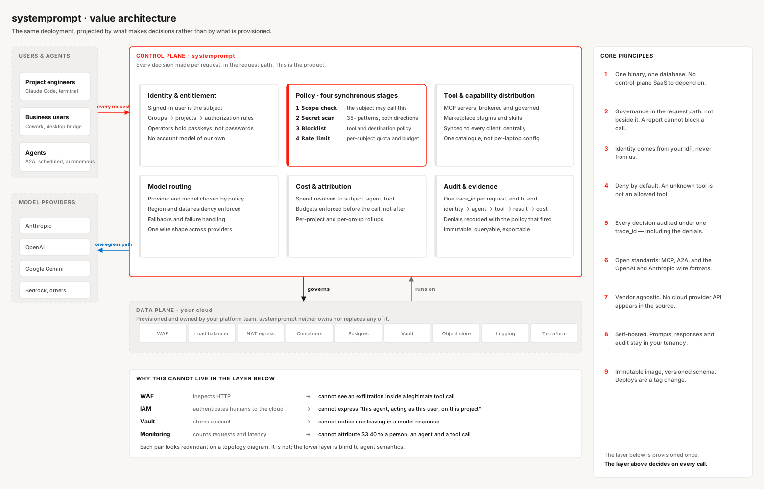
The layer below is provisioned once. The layer above decides on every call. That is the whole argument, and it is why the container looks small on a topology diagram without being small.
The source is docs/architecture/value-architecture.drawio in this repository —
an editable draw.io file, so the platform team can open it beside their own and
change it. Both it and the SVG above are generated from
scripts/make-value-architecture.py; edit the script, not the outputs.
Where the boundary is drawn
Almost every component in that diagram belongs to the platform team, not to the application. The gateway is the pair of container instances and a schema inside the managed PostgreSQL. That is deliberate: vendor agnosticism is only real if the software does not know which cloud it is on.
| Component | Owner | Notes |
|---|---|---|
| DNS, WAF, IAM, Internet Gateway | Platform team | The application has no configuration for any of them |
| Load Balancer, TLS termination, certificates | Platform team | The gateway serves plain HTTP on its port and expects TLS in front |
| VCN, subnets, NSGs, security lists | Platform team | |
| NAT Gateway, Service Gateway | Platform team | The NAT is the single egress path to model providers — one place to allowlist |
| OCIR, Resource Manager, Terraform | Platform team | The application ships as an image; it does not build on the target |
| Managed PostgreSQL (the instance) | Platform team | |
| Vault, Bastion, Logging, Monitoring, Notifications | Platform team | |
| Container image, stateless | Platform (this software) | One image, pinned by tag |
| Database schema and migrations | Platform (this software) | Versioned with the release, applied by its CLI |
/livez, /readyz, metrics port |
Platform (this software) | What the load balancer and monitoring consume |
| Outbound calls to model providers | Platform (this software) | Constrained in-process as well as at the NAT |
Six seams are where the two sides actually meet, and they are the only integration points worth specifying in the Terraform:
- Config and secrets. The node boots from a rendered profile directory plus a secrets source.
- Egress. All provider traffic leaves through the NAT Gateway. The gateway additionally validates every outbound URL that originated from a user or an agent, so the constraint holds on both sides of the boundary.
- Database access. Two distinct paths: the application to PostgreSQL on 5432 from the private subnet, and the bastion to 5432 for migrations and admin work. Migrations run as a one-shot on the bastion path or as a pre-deploy job — never as a side effect of application start once more than one replica exists.
- Blue/green with two live replicas. Two container instances in one backend set requires replica-safe job scheduling and shared session state.
- Identity, two planes. OCI IAM authenticates the platform team to the cloud. It does not authenticate end users to the application — that is passkey sign-in and the gateway's own authorization model. Do not assume IAM covers application access.
- Health and observability. Structured JSON logs on stdout (no agent required), a metrics port separate from the API port, and distinct liveness and readiness probes.
Current versus proposed, component by component
| Capability | Today | Proposed | Gap |
|---|---|---|---|
| Compute | One container instance | Two, blue/green behind one backend set | Supported; not yet run |
| Scheduled jobs across replicas | Instance-scoped claims, node and cluster policies | Same | None — already built |
| Session and identity state | In PostgreSQL | Same | None — already built |
| Liveness / readiness / metrics | /livez, /readyz, separate metrics port |
Same | None — already built |
| Provider egress | Single NAT path, in-process outbound URL validation | Same | None — already built |
| Database | One managed primary, DR replicas | Same; per-region replica reads still off | Deliberate — replica lag breaks read-after-write |
| Secrets | Rendered file, or environment | OCI Vault, with rotation | Gap 1 |
| Uploaded and generated files | Local directory, or a shared mount | Object storage | Gap 2 |
| Generated static content | Rendered to node-local disk on every node | Rendered once to shared storage | Gap 3 |
| Locally spawned MCP processes | Tracked by PID, not scoped per node | Scoped per instance | Gap 4 |
| Database TLS | Encrypted (sslmode=require) |
Certificate verified against a CA | Minor, open |
The four gaps, precisely
These are seams that exist in the code with drivers that have not been written. None of them is architectural rework, and none of them is reached by a single-node deployment.
Gap 1 — Secrets have no Vault provider. The secrets source resolves to a file or the environment, once, at boot, into process memory. A Vault provider is therefore two pieces of work, not one: the fetch driver, and — if leases and rotation are wanted rather than read-once-hold-until-restart — a renewal path. Worth deciding up front which of the two is being bought. Until then the Vault box in the diagram is satisfied operationally: the secret is stored in Vault and placed on the node by the deployment, which is how Deploy on Oracle Cloud does it today.
Gap 2 — File storage has no object-storage backend. File storage sits behind a vendor-agnostic interface with exactly one implementation: a local directory. Multiple replicas therefore need a shared mount, which OCI Container Instances do not hand you comfortably. The fix is an OCI Object Storage (or S3-compatible) backend behind the existing interface.
Gap 3 — Generated static content is written to node-local disk. The content pipeline renders HTML, sitemaps and feeds to a directory that is then served. With two replicas, whichever one ran the job has the fresh content and the other serves stale, unless that directory is the same shared mount. Same fix as gap 2.
Gap 4 — Locally spawned processes are not scoped per node. MCP servers and orchestrated agent processes started on a node are recorded in the shared database by raw process id, with liveness checked by signalling that id. On one node that is correct. On two, one node can read a row written by another and judge liveness against — or terminate — an unrelated local process holding the same id. The blast radius is bounded (remote MCP servers over HTTP are unaffected) but it is a real defect the moment two nodes both spawn local processes, and it is why multi-node boots are currently serialised. The fix is the instance-scoping the job scheduler already has.
The staged path
Deliberately incremental. Every component in the diagram is also a failure mode somebody has to be able to diagnose at three in the morning; adding them one at a time means you always know which one broke.
- Now — one region, one node. Managed PostgreSQL, load balancer with TLS, secrets injected, logs and metrics wired. Deployable in an afternoon, reversible in a minute. Reaches none of the four gaps.
- Next — Vault-backed secrets. Closes gap 1, the only one with a security dimension.
- Then — object storage. Closes gaps 2 and 3 together, and is the precondition for more than one replica serving files or content.
- Then — blue/green with two replicas. Needs gap 4 closed first.
- Then — WAF, multi-AZ, and whatever region story the business needs.
Each stage is documented here as it is actually run, not as it is planned. A line moves out of this page and into Deploy on Oracle Cloud when it has been proven on a real instance — that is the only thing that distinguishes the two pages.